
Introduction
A Limit Switch Box is a critical component used in valve automation systems to provide visual and electrical feedback on valve position. Whether it’s for a pneumatic, electric, or hydraulic actuator, a limit switch box ensures that the valve position can be accurately monitored and transmitted to a control system. In industrial automation, especially within sectors such as oil, gas, chemical, and water treatment, proper installation and wiring of limit switch boxes are essential to guarantee safe, reliable, and efficient operation.
In this article, we’ll guide you through how to install a limit switch box on a valve actuator, how to wire it correctly, and whether it can be mounted on different valve types. We’ll also explain practical tips from engineering experience and reference the high-quality manufacturing practices of Zhejiang KGSY Intelligent Technology Co., Ltd., a professional producer of valve intelligent control accessories.
Understanding the Function of a Limit Switch Box
A limit switch box—sometimes called a valve position feedback unit—serves as the communication bridge between the valve actuator and the control system. It detects whether the valve is in the open or closed position and sends a corresponding electrical signal to the control room.
Key Components Inside a Limit Switch Box
- Mechanical Cam Shaft: Converts the valve’s rotational movement into a measurable position.
- Micro Switches / Proximity Sensors: Trigger electrical signals when the valve reaches a preset position.
- Terminal Block: Connects the switch signals to external control circuits.
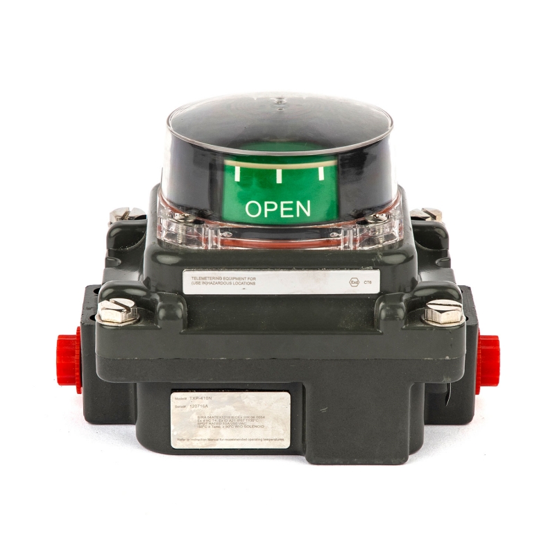
- Indicator Dome: Provides visual feedback of the valve’s current position.
- Enclosure: Protects the components from dust, water, and corrosive environments (often rated IP67 or explosion-proof).
Why It Matters
Without a limit switch box, operators cannot verify whether a valve has reached its intended position. This can lead to system inefficiency, safety risks, or even costly shutdowns. Therefore, correct installation and calibration of the switch box are crucial.
Step-by-Step Guide – How to Install a Limit Switch Box on a Valve Actuator
Step 1 – Preparation and Inspection
Before installation, ensure that the actuator and limit switch box are compatible. Check:
- Mounting standard: ISO 5211 interface or NAMUR pattern.
- Shaft dimensions: The actuator drive shaft should fit perfectly with the switch box coupling.
- Environment suitability: Verify explosion-proof or weatherproof grade if required by the process environment.
Tip: Zhejiang KGSY’s limit switch boxes come with standardized mounting brackets and adjustable couplings that fit most valve actuators directly, reducing the need for machining or modification.
Step 2 – Mounting the Bracket
The mounting bracket acts as the mechanical link between the actuator and the limit switch box.
- Attach the bracket to the actuator using appropriate bolts and washers.
- Make sure the bracket is firmly secured and level.
- Avoid overtightening—this can cause misalignment.
Step 3 – Coupling the Shaft
- Place the coupling adapter on the actuator shaft.
- Ensure that the coupling moves smoothly with the actuator rotation.
- Insert the limit switch box onto the bracket and align its internal shaft with the coupling.
- Tighten the fastening screws gently until the unit is secure.
Important: The switch box shaft must rotate exactly with the actuator shaft to ensure correct feedback positioning. Any mechanical offset can lead to incorrect signal feedback.
Step 4 – Adjusting the Indicator Dome
Once mounted, manually operate the actuator between the “Open” and “Close” positions to ensure:
- The indicator dome rotates accordingly.
- The mechanical cams inside trigger the switches at the correct position.
If misalignment occurs, remove the dome and re-adjust the cam or coupling until movement corresponds accurately.
How to Wire a Limit Switch Box
Understanding the Electrical Layout
A standard limit switch box typically includes:
- Two mechanical or inductive switches for open/close signal output.
- Terminal block for external wiring.
- Cable gland or conduit entry for wire protection.
- Optional feedback transmitters (e.g., 4–20mA position sensors).
Step 1 – Prepare the Power and Signal Lines
- Turn off all electrical sources before starting any wiring.
- Use shielded cables if your system is prone to electrical noise.
- Route the cable through the gland or conduit port.
Step 2 – Connect the Terminals
- Follow the wiring diagram provided with the product manual.
- Typically, terminals are labeled “COM,” “NO,” and “NC” (Common, Normally Open, Normally Closed).
- Connect one switch to indicate “Valve Open” and the other to “Valve Closed.”
- Tighten the screws firmly but avoid damaging the terminals.
Tip: KGSY’s limit switch boxes feature spring-clamp terminals, making wiring faster and more reliable than screw-type terminals.
Step 3 – Test the Signal Output
After wiring, power up the system and manually operate the valve actuator. Observe:
- If the control room or PLC receives correct “open/close” signals.
- If any polarity or position needs to be swapped.
If errors are found, recheck the cam alignment and terminal connection.
Can a Limit Switch Box Be Mounted on Any Type of Valve?
Not every valve type uses the same actuator interface, but modern limit switch boxes are designed for versatility.
Common Compatible Valves
- Ball Valves – quarter-turn, ideal for compact installations.
- Butterfly Valves – large-diameter valves requiring clear visual feedback.
- Plug Valves – used in corrosive or high-pressure conditions.
These valves usually pair with pneumatic or electric actuators that share standardized mounting interfaces, allowing universal compatibility with most limit switch boxes.
Special Considerations for Different Valve Types
- Linear valves (such as globe or gate valves) often require linear position indicators instead of rotary switch boxes.
- High-vibration environments may require reinforced mounting brackets and anti-loose screws.
- Explosion-proof zones demand certified products (e.g., ATEX, SIL3, or Ex d IIB T6).
KGSY’s explosion-proof limit switch boxes meet multiple international standards, including CE, TUV, ATEX, and SIL3, ensuring reliable operation in harsh environments.
Common Mistakes to Avoid During Installation
1. Misaligned Shaft Coupling
Incorrect shaft coupling alignment causes inaccurate feedback or mechanical stress, leading to switch damage.
Solution: Reposition the cam and retighten the coupling while the valve is at the midpoint.
2. Over-Tightened Bolts
Excessive torque may warp the enclosure or affect the internal mechanism.
Solution: Follow the torque values in the product manual (usually around 3–5 Nm).
3. Poor Cable Sealing
Improperly sealed cable glands allow water ingress, leading to corrosion or short circuits.
Solution: Always tighten the gland nut and apply waterproof sealing where necessary.
Practical Example – Installing a KGSY Limit Switch Box
A power plant in Malaysia installed over 200 KGSY limit switch boxes on pneumatic butterfly valves. The installation process involved:
- Mounting ISO 5211 standard brackets directly onto actuators.
- Using pre-wired terminal connectors for quick installation.
- Adjusting visual indicators for each valve position.
Result: Installation time reduced by 30%, and feedback accuracy improved by 15%.
Maintenance and Periodic Inspection
Even after successful installation, periodic maintenance ensures long-term reliability.
- Check screw tightness and cam position every 6 months.
- Inspect for moisture or corrosion inside the enclosure.
- Verify electrical continuity and signal response.
KGSY provides detailed user manuals and technical support for regular maintenance and recalibration.
Conclusion
Installing and wiring a limit switch box correctly is essential for maintaining safety, accuracy, and efficiency in valve automation systems. From mechanical mounting to electrical wiring, each step requires precision and understanding of the device’s structure. With modern, high-quality solutions like those from Zhejiang KGSY Intelligent Technology Co., Ltd., installation becomes faster, more reliable, and compatible with a wide range of valve actuators.
Post time: Oct-07-2025

