
n the fast-paced world of process automation, maintenance teams are often stretched thin, caught in a perpetual cycle of reacting to immediate equipment failures rather than preventing them. When it comes to automated valve packages, the heavy mechanical components—the pneumatic actuators and the valve bodies themselves—usually command the most attention. However, the true vulnerability of the system often lies in its smallest components: the limit switch boxes (valve position monitors).
These critical devices act as the “eyes” of your Distributed Control System (DCS). If a limit switch fails, the DCS goes blind, leading to false interlocks, dangerous product mixing, or unnecessary and highly expensive plant shutdowns.
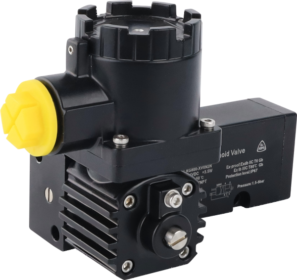
At Zhejiang KGSY Intelligent Technology Co., Ltd., we engineer our limit switch boxes (such as the standard APL series and the heavy-duty KG800 Ex d series) to provide years of reliable service. Nevertheless, like any electromechanical device operating in harsh industrial environments, they require a proactive maintenance strategy.
The question every plant manager asks is: How often should we actually be checking these switches? The answer is not a rigid one-size-fits-all number. It requires a tiered approach based on your specific operational environment. Here is a comprehensive guide to establishing a bulletproof maintenance schedule for your valve position monitors.
1. Determining Your Baseline Risk Profile
Before implementing a schedule, evaluate the specific application of the valve. The frequency of inspection is dictated by three primary variables:
-
Cycle Frequency: A control valve in a continuous batching process might stroke hundreds of times a day, rapidly wearing down mechanical micro-switches. Conversely, an Emergency Shutdown (ESD) valve might only stroke once a year during testing, risking internal component seizure from inactivity.
-
Environmental Severity: Is the switch box installed indoors in a climate-controlled water treatment plant, or outdoors on a North Sea oil platform exposed to saltwater spray, extreme UV radiation, and heavy pipeline vibration?
-
Component Technology: Traditional mechanical micro-switches (SPDT/DPDT) contain moving springs and metallic contacts that degrade over time. Solid-state inductive proximity sensors (NAMUR) have zero moving parts and inherently require far less maintenance.
Based on these factors, we recommend dividing your maintenance program into three distinct tiers: routine visual, semi-annual preventative, and annual turnaround.
2. Tier 1: The Routine Visual Inspection (Monthly to Quarterly)
This inspection requires no tools, no enclosure opening, and no Lockout/Tagout (LOTO) procedures. It is a rapid visual check performed by operators during regular plant walkdowns.
What to Check:
-
Visual Indicator Alignment: Glance at the 3D high-visibility dome on top of the limit switch box. Does it match the physical state of the valve? If the DCS says the valve is closed, and the pipeline is cold, but the dome says “OPEN,” you have an immediate mechanical disconnect that requires intervention.
-
External Enclosure Integrity: Inspect the outer shell for severe corrosion, impact damage, or chemical degradation. Ensure the shatterproof polycarbonate dome is not cracked.
-
Cable Gland Security: Look at the electrical entry point. Ensure the conduit or cable gland is not hanging loose, which would immediately compromise the IP67 weather seal and allow rainwater to funnel directly into the electronics.
Frequency: Monthly for high-vibration or outdoor corrosive environments; Quarterly for stable, indoor applications.
3. Tier 2: The Preventative Health Check (Bi-Annually)
This tier requires a qualified instrumentation technician to open the enclosure and verify the internal health of the electromechanical system. Standard LOTO procedures and hazardous area hot-work permits (if dealing with Ex d enclosures) must be observed.
What to Check:
-
The Moisture Inspection: Open the cover and meticulously inspect the inside of the housing. Look for micro-droplets on the enclosure walls or corrosion on the printed circuit board (PCB) and terminal blocks. If water is present, check the main O-ring seal, verify the cable glands are tightened, and consider retrofitting the enclosure with a breather drain to manage internal condensation.
-
Bracket Rigidity (The “Shake Test”): The mounting bracket (VDI/VDE 3845) is the critical link between the actuator and the switch. Ensure all stainless steel mounting bolts are tight. If the bracket vibrates or wiggles even slightly, the DCS signal will eventually suffer from jitter.
-
Wiring Fatigue: Pipeline vibration can cause standard internal “flying leads” to whip and eventually fray or loosen from their terminal blocks. Give each wire a gentle tug to ensure it is firmly clamped. (Note: KGSY’s KG800 series utilizes PCB-mounted terminals to completely eliminate this specific failure mode).
Frequency: Every 6 months. For highly critical safety loops, this should be expedited to every 3 to 4 months.
4. Tier 3: Full Turnaround & Calibration (Annually)
This is a comprehensive diagnostic procedure, typically aligned with a scheduled plant shutdown or major turnaround, designed to return the limit switch box to factory-new reliability.
What to Check:
-
Micro-Switch Continuity and Resistance: If using traditional mechanical switches, use a Digital Multimeter (DMM) to test the contact resistance. While slowly stroking the valve, listen for a crisp “click.” If the DMM shows fluctuating resistance when the switch is closed, the internal silver contacts have oxidized and the micro-switch must be replaced immediately.
-
Cam Re-Alignment: Verify that the internal cams strike the micro-switches exactly at the 0% and 100% travel limits. Over time, poorly designed set-screws can slip. (KGSY’s splined, spring-loaded cams prevent this, but verification is still best practice).
-
4-20mA Transmitter Calibration: If your limit switch box contains a continuous position transmitter, hook up a loop calibrator. Stroke the valve to fully closed and adjust the “Zero” potentiometer to exactly 4.00mA. Stroke fully open and adjust the “Span” to exactly 20.00mA. Verify there is no signal drift or ground loop interference.
-
Consumables Replacement: Replace the primary IP67 NBR or Silicone O-ring. Rubber degrades over time due to thermal cycling and ozone exposure. A fresh O-ring costs pennies but prevents thousands of dollars in water damage.
Frequency: Every 12 to 18 months, or during scheduled unit turnarounds.
5. Engineering Your Way Out of Maintenance
While a rigorous maintenance schedule is mandatory, the most cost-effective maintenance is the maintenance you don’t have to perform. By upgrading your hardware, you can drastically stretch the intervals between Tier 2 and Tier 3 inspections.
If your facility is burning through mechanical switches every few months due to high cycle rates or intense vibration, it is time to stop replacing them and start upgrading them. By specifying KGSY limit switch boxes equipped with NAMUR Inductive Proximity Sensors, you eliminate contact bounce, oxidation, and mechanical wear entirely.
Furthermore, by standardizing on highly engineered enclosures like the KGSY KG800 series—which features splined locking cams that cannot slip, robust PCB-mounted terminal architectures that resist vibration, and specialized breather drains that defeat condensation—you are no longer fighting the environment; you are mastering it.
Conclusion
A limit switch box is a small investment that protects a massive one. By shifting from a reactive “fix it when it breaks” mentality to a structured, three-tiered predictive maintenance schedule, plants can eliminate false interlocks, guarantee signal integrity, and maximize process uptime. Trust the operators to verify the visuals, trust the technicians to verify the internals, and trust KGSY to provide the rugged hardware foundation that makes it all possible.
Would you like me to design a “Maintenance Checklist” diagram to accompany this article? It could visually break down the Tier 1, Tier 2, and Tier 3 inspection steps for easy reference by plant technicians.
Post time: Apr-15-2026

