
In the world of process automation, the reliability of your Distributed Control System (DCS) is only as strong as its weakest physical link. Often, that link is the electromechanical micro switch residing inside your valve limit switch box.
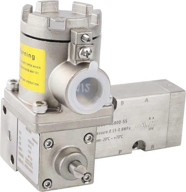
At Zhejiang KGSY Intelligent Technology Co., Ltd., we engineer our limit switch boxes—such as the rugged KG800 Ex d series and the versatile APL series—to withstand extreme industrial environments. However, traditional mechanical micro switches (typically V3-style SPDT switches) are inherently consumable components. Over millions of cycles, or under the strain of high-current arcing, severe pipeline vibration, and mechanical fatigue, the internal beryllium copper springs can break, or the silver contacts can oxidize and weld together.
When a switch fails, the DCS loses sight of the valve’s true position, leading to process interlocks and costly downtime. Fortunately, replacing a standard mechanical micro switch in a KGSY enclosure is a straightforward maintenance task that can be executed rapidly in the field.
This comprehensive guide walks your maintenance and instrumentation technicians through the safe, step-by-step process of diagnosing, removing, and replacing a faulty micro switch.
Phase 1: Safety Protocols and Preparation
Before touching a single tool, you must secure the work environment. Valve position monitors are often located in hazardous, explosive atmospheres and are integrated into live, high-pressure process lines.
1. Lockout/Tagout (LOTO) and Permits
- Electrical Isolation: Ensure the control loops feeding the limit switch box are completely de-energized. Lock out the circuit at the marshalling cabinet.
- Pneumatic Isolation: While you are only working on the electrical feedback, it is best practice to isolate the pneumatic air supply to the actuator so the valve cannot unexpectedly stroke and pinch fingers during calibration.
- Hazardous Area Permits: If you are working with an Explosion Proof (Ex d) enclosure like the KGSY KG800 in a Zone 1 or Zone 2 area, you must obtain a Hot Work Permit and verify the atmosphere is clear of combustible gases with a sniffer before removing the enclosure cover.
2. Required Tooling
Gather your instruments before climbing the scaffolding. You will need:
- A high-quality Digital Multimeter (DMM) with audible continuity function.
- A precision flathead screwdriver (typically 2.5mm or 3mm) for terminal blocks.
- A #1 or #2 Phillips head screwdriver.
- A set of metric Allen keys (Hex wrenches).
- Wire strippers and a crimping tool (if replacing wire ferrules).
- The correct replacement micro switch (ensure voltage and current ratings match the original).
Phase 2: Diagnostics – Verifying the Failure
Do not assume the switch is the problem until you test it. Signal loss can also be caused by crushed cables, blown DCS fuses, or a loose mounting bracket.
- Open the Enclosure: Unbolt the four captive screws on the KGSY switch box cover. Carefully lift the cover straight up to avoid dragging the visual indicator dome against the internal shaft.
- Identify the Terminals: A standard Single Pole Double Throw (SPDT) micro switch has three connection points:
○ COM (Common): The incoming voltage.
○ NC (Normally Closed): The circuit is complete when the switch is not pressed.
○ NO (Normally Open): The circuit is complete only when the switch is pressed.
- The Multimeter Test: Set your DMM to the continuity (beep) or Ohms (resistance) setting.
○ Place your probes on the COM and NC terminals of the suspect switch. It should read close to 0.0 Ohms (and beep).
○ Manually press the tiny metal lever or button on the micro switch. The DMM should immediately read O.L. (Open Loop) or infinite resistance, and the beep should stop.
○ Now, move the probe from NC to NO. When pressed, it should beep. When released, it should read Open Loop.
- Diagnosing the Result: If the switch fails to change state, if the resistance fluctuates wildly (indicating severe internal oxidation), or if it physically stays stuck pressed down, the switch is permanently compromised and must be replaced.
Phase 3: Removing the Faulty Micro Switch
Careful disassembly prevents damage to surrounding components and ensures you don’t lose track of your wiring schematic.
- Document the Wiring: Before disconnecting anything, take a clear photo with your industrial tablet or smartphone. Note exactly which color wire goes to the COM, NO, and NC terminals on the main terminal strip.
- Disconnect the Wires: Use your precision flathead screwdriver to loosen the terminal block screws and pull the wires associated with the broken switch free.
- Clear the Cams: To get the switch out, you may need to move the striking cams out of the way. With KGSY’s tool-less splined cams, simply push the spring-loaded cam downward along the shaft and rotate it 90 degrees away from the switch roller.
- Unbolt the Switch: Standard mechanical switches are usually stacked and secured to the internal bracket by two long, thin machine screws. Carefully hold the nuts on the back (if not tapped directly into the bracket) and unscrew the bolts. Slide the broken switch out of the housing.
Phase 4: Installing and Wiring the New Switch
Precision during installation guarantees maximum mechanical lifespan for the new component.
- Mounting the New Switch: Slide the new micro switch into the exact position of the old one. Reinsert the two long mounting screws.
○ Pro Tip: Do not overtighten these screws. The body of a micro switch is made of hard, brittle phenolic plastic. Excessive torque will crack the casing, instantly ruining the new switch. Tighten until snug and secure.
- Prepare the Wires: Inspect the stripped ends of the copper wires. If the copper is frayed or oxidized, snip it off, strip back exactly 5mm to 7mm of fresh insulation, and crimp on a new insulated wire ferrule. Bare, frayed wires are the leading cause of internal short circuits.
- Re-terminate: Route the wires cleanly back to the terminal block, referencing the photo you took earlier. Insert the wire into the terminal and tighten the screw firmly. Perform a gentle “tug test” on each wire to ensure it is solidly clamped.
Phase 5: Re-Calibration (The KGSY Quick-Set Method)
Now that the switch is wired, you must synchronize the mechanical cam with the physical stroke of the valve. The DCS needs to know exactly when the valve hits 0% or 100% travel.
- Stroke the Valve: Have the control room slowly stroke the pneumatic actuator to the desired limit (e.g., fully closed).
- Set the Splined Cam: This is where KGSY’s engineered internals shine. You do not need an Allen key to adjust microscopic set-screws. Simply push the color-coded cam (usually Red for Close, Green for Open) down against its internal spring to disengage it from the splined main shaft.
- Find the Actuation Point: Rotate the cam smoothly until the flat edge or the lobe just presses against the roller arm of your newly installed micro switch. You will hear a distinct, crisp “click.”
- Lock it in Place: Release the downward pressure on the cam. The internal spring will push the cam back up, locking the splines together. The cam is now permanently mechanically locked to the shaft and is immune to pipeline vibration.
Phase 6: Final Sealing and Commissioning
The repair is not complete until the environmental integrity of the enclosure is restored.
- Inspect the O-Ring: Look closely at the primary IP67 O-ring sitting in the groove of the enclosure base. Clean out any dust or debris. If the rubber looks dry or flattened, apply a very light coat of silicone dielectric grease. If it is cracked, replace it immediately to prevent water ingress.
- Secure the Cover: Place the KGSY cover back onto the base, ensuring the visual indicator aligns correctly with the shaft orientation. Tighten the four captive cover bolts in a diagonal, cross-pattern (like changing a car tire). This ensures even pressure across the IP67 seal.
- Live Test: Remove the LOTO locks. Ask the control room to stroke the valve fully open and fully closed multiple times. Verify that the DCS receives a clean, instantaneous, jitter-free signal at both limits.
Conclusion
By following standard diagnostic procedures and taking advantage of KGSY’s modular, vibration-resistant internal architecture, replacing a micro switch takes minutes, not hours.
However, if your facility is replacing mechanical switches on the same valve every few months due to extreme vibration, high cycle rates, or corrosive chemical fumes, it is time to upgrade the technology. Contact Zhejiang KGSY Intelligent Technology Co., Ltd. to discuss retrofitting your standard enclosures with solid-state, non-contact Inductive Proximity Sensors (NAMUR), which have zero moving parts and are impervious to mechanical wear.
Post time: Apr-08-2026

