
In the world of process automation, safety isn’t just a goal—it’s a regulatory mandate. Many industrial facilities begin their journey with general-purpose equipment, such as the widely used APL-210 series limit switch boxes, which are excellent for non-hazardous, weatherproof applications. However, as plants expand or process media becomes more volatile, areas that were once considered “safe” may be reclassified as Zone 1 or Zone 2 hazardous areas.
When a facility is reclassified, general-purpose monitors must be upgraded to certified explosion-proof hardware. Transitioning from the APL-210 to the heavy-duty ALS-500 explosion-proof series is one of the most common retrofits in the valve automation industry. This guide provides a comprehensive technical roadmap for engineers and maintenance teams to execute this upgrade safely and efficiently.
1. The Core Motivation: Why Retrofit?
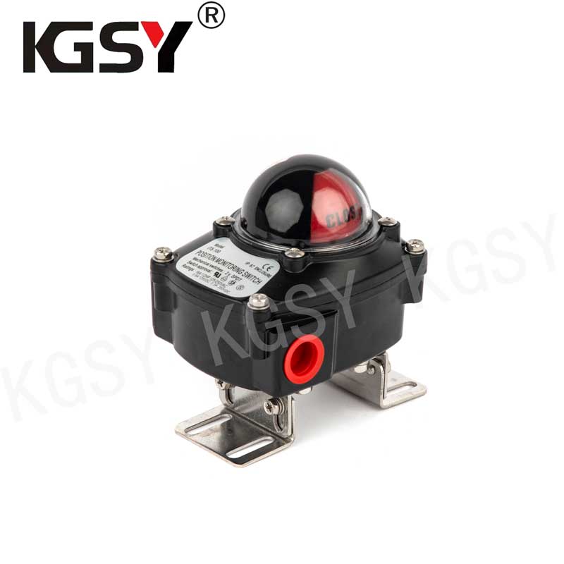
The primary driver for moving from an APL-210 to an ALS-500 is Explosion Protection (Ex d).
The APL-210 is a rugged, IP67-rated weatherproof monitor, but it is not designed to contain an internal explosion. In a hazardous environment—where flammable gases, vapors, or mists are present—any electrical spark inside a limit switch box could ignite the surrounding atmosphere.
The ALS-500 series, manufactured by Zhejiang KGSY Intelligent Technology Co., Ltd., is an Ex d (Flameproof) enclosure. Unlike standard boxes, the ALS-500 is engineered to:
-
Contain an internal explosion: If a spark ignites gas inside the box, the heavy-duty aluminum housing remains intact.
-
Cool escaping gases: Precision-machined “flame paths” allow pressure to vent but cool the flame so it cannot ignite the external environment.
-
Meet Global Standards: The ALS-500 holds ATEX and IECEx certifications, ensuring compliance with international safety laws.
2. Technical Comparison: APL-210 vs. ALS-500
Before starting the physical retrofit, it is vital to understand the hardware differences to ensure your mounting and wiring infrastructure can handle the new equipment.
| Feature | APL-210 (General Purpose) | ALS-500 (Explosion Proof) |
| Protection | Weatherproof (IP67) | Flameproof (Ex d IIC T6) |
| Housing | Die-cast Aluminum / Polyester Coating | Heavy-duty Die-cast Aluminum |
| Shaft | Standard Stainless Steel | Heavy-duty SS NAMUR Shaft |
| Cable Entry | 2 x NPT 1/2″ | 2 x NPT 3/4″ (or M20) |
| Mechanical Strength | Standard | High Impact / High Vibration |
The ALS-500 has a larger footprint and is significantly heavier than the APL-210. This mass is necessary for its explosion-containment rating, but it requires more rigid mounting support.
3. Pre-Retrofit Preparation
A successful retrofit begins long before the first bolt is turned. You must verify three critical compatibility factors:
A. Mounting Bracket Integrity
The APL-210 often uses lightweight, stamped metal brackets. Because the ALS-500 is heavier and often installed in vibration-prone hazardous zones, these flimsy brackets are insufficient. You must specify a heavy-gauge stainless steel VDI/VDE 3845 (NAMUR) bracket. Reusing an old APL bracket will lead to shaft misalignment and premature failure of the switch box.
B. Electrical Infrastructure
The ALS-500 typically features 3/4″ NPT cable entries, whereas the APL-210 often uses 1/2″ NPT. You will likely need to replace your cable glands. Important: You must use certified explosion-proof (Ex d) cable glands. Standard weatherproof glands are strictly prohibited in hazardous zones.
C. Hazardous Area Permits
Since the retrofit occurs in a potentially explosive zone, you must obtain “Hot Work” permits if using power tools, and ensure the area is sniffed for gas before the electrical loop is opened.
4. Step-by-Step Retrofit Procedure
Step 1: Isolation and LOTO
Always observe Lockout/Tagout (LOTO) procedures. Isolate the electrical power to the limit switch loop at the control cabinet. If the switch box is part of an interlock, ensure the DCS (Distributed Control System) is in bypass mode. Isolate the pneumatic air supply to the actuator to prevent the valve from stroking during the retrofit.
Step 2: Removal of the APL-210
Disconnect the wiring and remove the existing cable glands. Unscrew the four bolts connecting the APL-210 to the bracket. If the bracket shows any signs of corrosion or flex, remove it as well.
Step 3: Bracket Installation
Mount the new, rigid stainless steel NAMUR bracket to the actuator. Ensure it is perfectly centered over the actuator pinion. Use star washers and threadlocker to prevent the bracket from vibrating loose—a common cause of signal jitter in high-cycle applications.
Step 4: Mounting the ALS-500
Align the flat shaft of the ALS-500 with the slot on the actuator pinion. Lower the ALS-500 onto the bracket and secure it with four stainless steel bolts.
-
Engineering Tip: Rotate the valve manually to ensure the shaft turns freely without binding. Any resistance here indicates a misalignment that will snap the shaft over time.
Step 5: Wiring and Sealing (The Most Critical Step)
Pull your cables through the new Ex d certified cable glands. Wire the terminals according to the ALS-500 schematic.
-
Grounding: Explosion-proof units must be grounded both internally and externally to the enclosure.
-
Flame Paths: Ensure the machined surfaces of the cover and body are clean and free of scratches. These surfaces form the “flame path.” Never use a gasket or paint on these surfaces.
Step 6: Setting the Splined Cams
The ALS-500 features KGSY’s “Quick-Set” cam system. Unlike cheap units that use set-screws, these cams are splined and spring-loaded. Push down, rotate to the trip point for Open and Closed positions, and release. They interlock with the shaft, making it impossible for them to slip due to vibration.
5. Avoiding Common Retrofit Pitfalls
Through years of field analysis, we have identified three mistakes that frequently compromise a retrofit:
-
Using the Wrong Thread Type: Forcing a metric M20 gland into an NPT 3/4″ entry destroys the threads and invalidates the explosion-proof rating. Always check the stamped thread type on the housing.
-
Neglecting Conduit Seals: In many Zone 1 jurisdictions, a conduit seal (poured fitting) must be installed within 18 inches of the enclosure. Check your local electrical code (NEC or IEC) to ensure compliance.
-
Compromising the IP Rating: While the ALS-500 is explosion-proof, it still needs to be weatherproof. Ensure the O-ring is seated correctly before tightening the cover bolts to prevent moisture ingress and internal corrosion.
6. Long-Term Benefits and ROI
While an ALS-500 carries a higher initial cost than an APL-210, the Return on Investment (ROI) is realized through:
-
Regulatory Peace of Mind: You are fully compliant with insurance and safety audits.
-
Enhanced Durability: The ALS-500 is built for heavy industry. It resists mechanical shock better than general-purpose units, leading to fewer maintenance interventions.
-
Process Stability: Better shaft support and splined cams mean your DCS receives more accurate, reliable feedback, reducing false alarms and unnecessary plant shutdowns.
Conclusion
Upgrading from the APL-210 to the ALS-500 is more than a hardware swap; it is a commitment to industrial safety. By following this retrofit guide—focusing on rigid mounting, certified sealing, and precision calibration—maintenance teams can ensure their valve automation remains a robust, fail-safe link in their process chain.
For facilities operating in the chemical, oil and gas, or heavy processing sectors, the ALS-500 is the gold standard for hazardous area feedback. Protect your capital assets and your personnel by choosing the engineered resilience of the KGSY explosion-proof series.
Post time: May-27-2026

