
When your limit switch box stops functioning properly, it can disrupt entire process control systems in industrial applications. Limit switch boxes are essential components for valve automation, providing position feedback and signaling whether a valve is open or closed. However, like all mechanical and electrical devices, they can experience faults due to wiring problems, sensor damage, or calibration drift. In this comprehensive guide, we will explore how to identify, troubleshoot, and test a faulty limit switch box effectively.
Understanding the Function of a Limit Switch Box
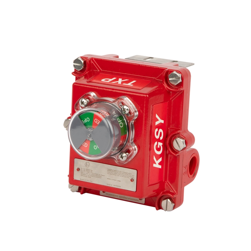
A limit switch box, also known as a valve position indicator, is mounted on a valve actuator to provide electrical feedback on the valve’s position. It translates the actuator’s mechanical motion into an electrical signal sent to the control system. In automated industries such as chemical, oil & gas, or water treatment, this feedback is critical for safety and process precision.
Key Components Inside a Limit Switch Box
- Mechanical cam or shaft: Connects to the valve stem to sense position.
- Micro switches or proximity sensors: Detect open or closed positions.
- Terminal blocks: Provide wiring connections to external circuits.
- Indicator dome: Visually shows the valve’s position.
- Enclosure: Protects internal parts from moisture, dust, and corrosion (rated IP65, IP67, etc.).
Common Reasons Why a Limit Switch Box Stops Working
When your limit switch box fails to provide accurate signals, several underlying issues may be to blame. Let’s look at the most frequent causes:
1. Electrical Connection Issues
Loose wiring, corroded terminals, or poor grounding can lead to intermittent or total signal failure. Check the terminal block and wiring diagram to confirm that the cables are properly secured and correspond to the control system’s input channels.
2. Mechanical Misalignment
If the actuator shaft and the limit switch box cam are not correctly aligned, the mechanical movement will not trigger the switches accurately. Misalignment often occurs during installation or after extended vibration and use.
3. Damaged or Worn Micro Switches
Over time, the internal micro switches or proximity sensors can wear out, causing false signals or no signal at all. Using high-quality switches rated for industrial environments reduces the risk of premature failure.
4. Water or Dust Ingress
Improper sealing or low IP-rated enclosures (below IP65) can allow moisture and dust to enter the box. This leads to corrosion, short circuits, or mechanical blockage. Choosing a limit switch box with IP67 protection ensures long-term reliability in harsh environments.
5. Calibration Errors
If the cams inside the box are not properly set, the feedback signal will not match the actual valve position. Calibration must be done accurately during setup and verified periodically.
6. External Control System Problems
Sometimes, the issue lies not within the limit switch box but in the connected PLC, DCS, or relay system. Always verify that the input modules and power supply are functioning correctly before replacing the limit switch box.
How to Troubleshoot a Limit Switch Box Step by Step
Troubleshooting requires a systematic approach to isolate the fault. Below is a step-by-step process that maintenance technicians can follow.
Step 1: Safety First
Before opening or inspecting any electrical device, ensure that power is disconnected and the valve actuator is in a safe position. Wear appropriate PPE such as insulated gloves and eye protection.
Step 2: Visual Inspection
Check the enclosure for cracks, moisture, or corrosion. Verify that the indicator dome moves freely and that all screws and covers are properly tightened.
Step 3: Verify Wiring
Use the manufacturer’s wiring diagram to confirm that each wire is correctly connected. Look for frayed wires, loose terminals, or short circuits. Tighten connections as necessary.
Step 4: Test Micro Switch Operation
Manually operate the valve or actuator while listening for a click sound inside the switch box. Each position (open/close) should correspond to a switch activation. If no sound is heard, the switch may be faulty.
Step 5: Electrical Continuity Test
Using a multimeter, measure the continuity between the common (COM) and normally open (NO) or normally closed (NC) terminals. When the switch is engaged, continuity should exist between COM and NO. When released, it should exist between COM and NC.
Step 6: Check Indicator Alignment
Ensure the position indicator aligns correctly with the valve’s open and closed markings. Misalignment may cause false visual readings.
Step 7: Inspect Cams and Actuator Coupling
Remove the top cover and check if the cam moves smoothly with the actuator shaft. If it’s slipping or not rotating properly, retighten the set screws or replace the cam if worn.
How to Test a Limit Switch Box
Using a Multimeter
Set the multimeter to continuity mode. Connect one probe to the COM terminal and the other to the NO terminal. Operate the valve manually. When the valve opens, you should see continuity on the open switch; when closed, continuity should move to the closed switch. Lack of continuity indicates a wiring or switch fault.
Using a Control System Simulation
If connected to a PLC, observe the feedback signals on the control panel. The system should display “Valve Open” or “Valve Closed” based on the actuator’s actual movement. If signals do not change, further inspect the internal switches or wiring.
Environmental and Vibration Testing
In some industrial applications, vibration and environmental stress testing are performed to confirm the box’s long-term stability. High-quality boxes such as the KGSY limit switch box undergo IP67 sealing and SIL3 reliability testing before shipment.
Preventive Maintenance Tips
1. Routine Inspection
Inspect the limit switch box monthly for signs of wear, corrosion, or water ingress. Early detection prevents costly downtime.
2. Recalibration Schedule
Calibrate the cams every six months or after any actuator maintenance. This ensures that the electrical signals match the actual valve position.
3. Use Genuine Parts
Always use manufacturer-approved spare parts for replacement switches or indicator domes. Generic parts may not provide the same IP rating or durability.
4. Environmental Sealing
For outdoor or offshore installations, use weatherproof enclosures with IP67 or higher protection to avoid moisture-related failures.
Why Choose KGSY Limit Switch Boxes for Reliable Performance
Zhejiang KGSY Intelligent Technology Co., Ltd. is a professional high-tech manufacturer specializing in valve intelligent control accessories. The company’s main products include valve limit switch boxes, solenoid valves, air filters, pneumatic actuators, and valve positioners. With certifications such as CCC, TUV, CE, ATEX, SIL3, and IP67, KGSY ensures that its limit switch boxes deliver consistent performance even in harsh industrial conditions.
KGSY’s research and development team integrates advanced design techniques and precision testing instruments to ensure reliability, accuracy, and safety. Whether you are working in petroleum, natural gas, or water treatment industries, KGSY limit switch boxes provide dependable feedback and robust environmental protection.
Conclusion
When your limit switch box is not working, systematic troubleshooting, proper testing, and regular maintenance are key to restoring functionality. By following the diagnostic steps above, you can identify wiring issues, switch malfunctions, or calibration problems effectively. Investing in a high-quality, IP67-rated limit switch box—such as those from KGSY Intelligent Technology—can significantly reduce downtime, improve safety, and extend equipment life.
Post time: Oct-11-2025

