
Imagine an operator walking the process line during a routine safety inspection. They glance up at a critical pneumatic ball valve on a cooling water line. The high-visibility 3D dome on top of the limit switch box brightly displays “OPEN” in yellow. However, when they cross-reference the Distributed Control System (DCS) tablet, the electronic feedback definitively states the valve is “CLOSED.” Furthermore, the pipeline is cold—no fluid is flowing.
This scenario—a direct contradiction between the physical visual indicator and the actual valve state—is one of the most dangerous and confusing situations in process automation. It undermines operator confidence, complicates lockout/tagout (LOTO) procedures, and can lead to catastrophic manual override errors.
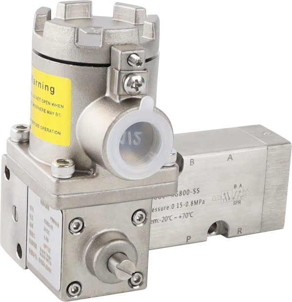
At Zhejiang KGSY Intelligent Technology Co., Ltd., we manufacture thousands of APL, KG800, and FC800 series limit switch boxes annually. Our 3D polycarbonate visual indicators are designed to be seen clearly from up to 50 meters away. However, if the visual indicator is lying to you, the problem usually stems from installation errors, mechanical slippage, or a misunderstanding of actuator mechanics.
Here is a comprehensive, step-by-step engineering guide to diagnosing and fixing a false visual indicator on your automated valve package.
1. The Anatomy of a False Reading: How the Indicator Works
Before troubleshooting, it is essential to understand the mechanical linkage. A limit switch box does not independently “know” what the valve is doing. It is a slave to the actuator.
The industry standard for mounting these accessories is VDI/VDE 3845 (NAMUR). The top pinion of the pneumatic actuator features a slotted shaft. The limit switch box has a corresponding flat bottom shaft that slots into the actuator. As the actuator turns the valve stem (typically 90 degrees for quarter-turn valves like ball or butterfly valves), it simultaneously turns the limit switch box shaft.
The visual indicator dome sits on the very top of the limit switch box shaft. Therefore, if the dome is displaying the wrong position, the mechanical sequence from the valve ball $\rightarrow$ actuator stem $\rightarrow$ switch box shaft $\rightarrow$ indicator dome has been interrupted or misaligned.
2. Cause 1: The 90-Degree Installation Error (Human Error)
By a wide margin, the most common reason for a mismatched indicator is human error during the initial commissioning or after a maintenance shutdown.
The Problem:
Most 3D visual indicators (like the standard Red/Yellow KGSY domes) are secured to the main internal shaft by four small screws, or they are integrated into the main cover. During maintenance, a technician might remove the switch box cover to wire the terminals. When they put the cover back on, or reattach the indicator dome, they inadvertently rotate it 90 degrees before tightening the screws.
Because the mounting bolt pattern is perfectly square, the dome fits perfectly whether it is facing the right way or 90 degrees off. The valve is closed, the internal micro-switches send a “closed” signal to the DCS, but the dome was bolted on facing “OPEN.”
The Solution:
-
Verify the actual physical state of the valve (check the flow or the scribe line on the valve stem).
-
Unscrew the clear polycarbonate outer dome.
-
Loosen the inner colored indicator piece.
-
Lift it off the shaft, rotate it exactly 90 degrees so it matches the true valve state, and securely bolt it back down.
-
Stroke the valve a few times to ensure it tracks perfectly.
3. Cause 2: Mounting Bracket Slippage and Vibration
If the indicator was correct yesterday but is wrong today, human error during assembly is ruled out. The next culprit is mechanical slippage.
The Problem:
Limit switch boxes are mounted to actuators using stainless steel or carbon steel NAMUR brackets. If the installation team did not use proper spring washers, or if the pipeline experiences severe hydraulic shock (water hammer) or heavy vibration, the bracket bolts can vibrate loose.
When the bracket loosens, the entire limit switch box can shift or rotate slightly on top of the actuator. In severe cases, the box lifts up just enough for the limit switch shaft to pop out of the NAMUR slot on the actuator. The actuator turns the valve, but the switch box shaft (and the visual dome) remains stationary.
The Solution:
-
Conduct a physical “shake test” on the limit switch box. It should be absolutely rigid.
-
If loose, unbolt the bracket, inspect the NAMUR slot for wear or rounding off (which happens if it spins freely), and re-seat the shaft.
-
The KGSY Best Practice: When utilizing KGSY limit switch boxes on high-vibration lines, always use heavy-duty stainless steel brackets with star washers (toothed lock washers) and thread-locking fluid (like Loctite) on the mounting bolts to guarantee zero bracket creep.
4. Cause 3: Fail-Safe Confusion (Air-to-Open vs. Air-to-Close)
Sometimes, the mismatch occurs because the actuator’s fail-safe action was misunderstood during the valve package assembly.
The Problem:
Pneumatic actuators often feature a spring-return mechanism.
-
Fail-Close (Air-to-Open): Springs drive the valve closed when air pressure is lost.
-
Fail-Open (Air-to-Close): Springs drive the valve open when air pressure is lost.
If an automation team receives a Fail-Open actuator but assumes it is a standard Fail-Close, they might mount the limit switch box while the valve is in its resting (open) state, but set the indicator dome to “Closed” out of habit. When air is applied, the valve closes, but the indicator spins to “Open.” The entire cycle is perfectly inverted.
The Solution:
Consult the actuator’s nameplate to verify the spring-return action. Bleed the air supply to force the valve into its fail-safe resting state. Physically verify if the valve is open or closed, and then align the visual indicator dome to match this definitive resting state.
5. Cause 4: Internal Shaft or Coupling Shearing
This is the most severe cause of a visual mismatch and requires hardware replacement.
The Problem:
If a valve seizes due to pipeline debris or chemical crystallization, the pneumatic actuator will apply maximum torque to try and move it. If a manual gear override is aggressively applied by an operator trying to force a jammed valve, immense torsional stress is transferred upward into the limit switch box shaft.
In lower-quality limit switch boxes, the internal plastic or cast-alloy shaft can shear cleanly in half, or the bottom NAMUR tabs can snap off. The actuator might eventually move the valve, but the broken top half of the switch box shaft (holding the visual dome) remains frozen in place.
The Solution:
-
Remove the limit switch box completely from the bracket.
-
Inspect the bottom driving shaft. If the metal tabs are sheared off, or if you can spin the top visual indicator freely by hand without the bottom shaft moving, the internal shaft is destroyed.
-
The KGSY Advantage: KGSY engineers the primary shafts of our KG800 and FC800 series from high-strength stainless steel (SS304 or SS316). They are designed to withstand exceptional torsional loads without shearing, ensuring that the visual indicator and the micro-switch cams remain inextricably linked to the actuator’s actual position.
Conclusion: Trust, but Verify
A visual indicator is designed to provide immediate, at-a-glance safety information to plant personnel. When it displays false information, it is worse than having no indicator at all. By standardizing your maintenance procedures to cross-check the actual valve state, the NAMUR bracket rigidity, and the indicator alignment during every turnaround, you can eliminate this dangerous ambiguity.
At Zhejiang KGSY Intelligent Technology Co., Ltd., we believe that visual feedback should be as reliable as the electronic signal. Our shatterproof polycarbonate domes, captive cover bolts (which prevent 90-degree misalignment during field maintenance), and solid stainless-steel shafts ensure that what you see on the pipeline is exactly what is happening inside the pipe.
Are you looking to standardize the valve automation packages across your facility to prevent these types of mechanical mismatches? We will be demonstrating our full range of foolproof limit switch boxes at CHEMUK 2026 at the NEC in Birmingham this coming May.
Would you like me to draft a LinkedIn post promoting KGSY’s presence at CHEMUK 2026, highlighting our solutions for these exact field-level troubleshooting problems?
Post time: Apr-08-2026

