
In the era of Industry 4.0 and the Industrial Internet of Things (IIoT), processing plants are smarter, faster, and more connected than ever before. Plant managers can monitor pump vibration, tank levels, and automated control valve positions from a Distributed Control System (DCS) hundreds of miles away. Yet, despite these massive leaps in digital transformation, almost every chemical plant, refinery, and food processing facility still relies on a vast network of manual valves.
These manual ball, butterfly, and gate valves are critical for isolation, bypass routing, and maintenance lock-outs. However, they present a massive blind spot for modern control systems. Because they are operated by human hands rather than pneumatic or electric actuators, they are “blind” to the DCS. If an operator accidentally leaves a manual bypass valve open, the control room won’t know until a tank overflows, a batch is ruined, or an environmental spill occurs.
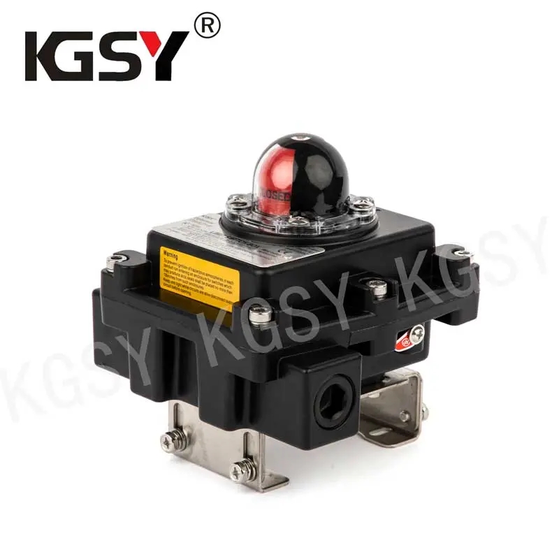
To bridge this dangerous gap, facilities are increasingly retrofitting their manual valves with limit switch boxes (valve position monitors). But adding electronic monitoring to a manual valve isn’t a simple plug-and-play operation. It requires a critical, precision-engineered mechanical bridge: the custom mounting bracket.
Here is a comprehensive guide to understanding, engineering, and implementing custom mounting brackets to successfully adapt switch boxes to manual valves.
1. The NAMUR Disconnect: Why Customization is Mandatory
To understand why custom brackets are necessary, we must look at how automated valves are built. When you purchase a pneumatic actuator, the top of the unit almost universally conforms to the NAMUR VDI/VDE 3845 standard. This standard dictates the exact bolt hole dimensions and shaft height, allowing any standardized limit switch box to bolt on perfectly in minutes using an off-the-shelf bracket.
Manual valves, however, have no such top-works standardization. A manual valve is designed strictly for a human hand to operate a lever or a handwheel. The top of the valve body might have an ISO 5211 mounting flange (intended for automation), but the handle often obstructs it. Worse, older legacy valves may have no mounting holes at all, featuring odd cast shapes, varying stem heights, and proprietary handle designs.
Because there is no “standard” manual valve top-works, there can be no standard bracket. Adapting a switch box requires a custom-fabricated mounting kit designed specifically for the exact make, model, and size of the valve in question.
2. Anatomy of a Custom Mounting Kit
A proper retrofit kit is not just a piece of bent metal. It is a precision-engineered assembly that must transfer mechanical motion flawlessly while withstanding industrial environments. A complete custom mounting kit typically consists of three primary components:
A. The Bracket Body
This is the structural frame that attaches to the valve body and provides a stable platform for the switch box. It must be designed to clear the manual handle, allowing the operator full range of motion without pinching their fingers or striking the electronic enclosure. The top of the bracket is pre-drilled to match the NAMUR footprint of the switch box.
B. The Drive Coupler (Stem Adapter)
The switch box has a standard shaft (usually a NAMUR slot), but the manual valve stem could be a square, a double-D, a keyed round shaft, or a threaded rod. The drive coupler is a custom-machined piece of metal that mates the unique geometry of the valve stem to the standardized slot of the switch box.
C. Fasteners and Standoffs
Industrial-grade stainless steel bolts, lock washers, and sometimes threaded standoffs are required to secure the assembly tightly against pipeline vibration.
3. Engineering Considerations for Custom Brackets
Designing a custom bracket requires a deep understanding of mechanical engineering and field conditions. When specifying or designing a retrofit kit, several critical factors must be addressed to ensure long-term reliability.
Material Selection: The Case for Stainless Steel
In a typical plant environment, carbon steel brackets will quickly succumb to rust, while lightweight aluminum might flex under stress. The industry standard for custom brackets is 304 or 316 Stainless Steel. Stainless steel provides exceptional rigidity, ensuring that pipeline vibration does not cause the bracket to resonate and shatter the switch box housing. Furthermore, it resists corrosion from harsh chemical washdowns, coastal salt air, and general atmospheric degradation.
Absolute Concentricity
The single most common cause of premature switch box failure in retrofits is poor concentricity. If the center of the valve stem does not align perfectly with the center of the switch box shaft, the drive coupler will create lateral stress (side-load) on the switch box bearings. Over time, this eccentric rotation will carve out the internal seals of the switch box, leading to moisture ingress, electrical shorts, and total failure. A custom bracket must be CNC-machined or precision laser-cut to ensure dead-center alignment.
Clearing the Handle Operations
The bracket must “bridge” over or around the manual handle. Engineers must account for the operator’s heavy protective gloves. If the bracket sits too low, the operator cannot safely grasp the handle. If it sits too high, the extended drive coupler becomes a weak point prone to twisting (torsional flex). The design must strike a perfect balance between ergonomic clearance and mechanical stability.
4. Tackling Valve Geometry: Rotary vs. Rising Stem
The type of manual valve dictates the complexity of the custom bracket design.
Quarter-Turn Valves (Ball, Butterfly, Plug): These are the easiest to retrofit. The stem simply rotates 90 degrees. The custom bracket is usually a “bridge” design that bolts onto the valve’s ISO pad, arches over the handle, and supports the switch box on top. The drive coupler connects the rotating stem directly to the switch box.
Multi-Turn / Rising Stem Valves (Gate, Globe): These present a severe engineering challenge. As the handwheel turns, the stem does not just rotate; it moves linearly up and down. You cannot attach a standard rotary switch box directly to a stem that rises 10 inches into the air. For these valves, engineers must design complex custom bracketry that uses linear proximity triggers, specialized slotted lever arms, or linear-to-rotary conversion mechanisms. Often, the bracket mounts to the valve yoke, and triggers are clamped to the rising stem to trip inductive sensors at the “fully open” and “fully closed” limits.
5. The Retrofitting Workflow
Successfully executing a manual valve retrofit project involves a systematic approach to avoid expensive field modifications:
-
Site Audit & Measurement: A technician measures the exact dimensions of the valve stem, handle clearance, and mounting bolt patterns using digital calipers.
-
CAD Design: Engineers create a 3D CAD model of the bracket and drive coupler, simulating the rotation to ensure there are no physical clashes.
-
Precision Fabrication: The bracket is laser-cut and folded via CNC press brakes, while the drive coupler is CNC-milled.
-
Field Installation: The plant is isolated, the handle is temporarily removed, the bracket is bolted in place, the handle is reattached, and the switch box is mounted.
-
Calibration and DCS Integration: The cams inside the switch box are set, and the wiring is routed back to the control system, bringing the blind valve into the digital light.
6. The ROI of Adapting Manual Valves
While fabricating custom stainless steel brackets and purchasing switch boxes requires capital investment, the Return on Investment (ROI) is rapid and measurable.
By bringing manual valves into the DCS loop, facilities drastically reduce the risk of human error. You eliminate the need for operators to walk miles of pipeline with a clipboard just to verify valve positions before a batch run. More importantly, you create a digital safety interlock; the DCS can be programmed to halt a pump from starting if a critical manual suction valve is closed, saving tens of thousands of dollars in ruined equipment and downtime.
Conclusion
The custom mounting bracket is the unsung hero of modern plant safety upgrades. It is the vital mechanical translation layer that allows rugged, reliable switch boxes to interface with legacy manual valves. By demanding precision engineering, stainless steel construction, and perfect concentricity in your custom brackets, you can successfully eliminate your facility’s digital blind spots—ensuring that every valve, manual or automated, contributes to a safer, more efficient process environment.
Post time: May-27-2026

