
Introduction
A Limit Switch Box plays a critical role in industrial valve automation by providing real-time feedback about the valve’s position—open, closed, or somewhere in between. However, simply having a high-quality switch box isn’t enough; its performance depends heavily on how well it’s installed, calibrated, and maintained.
This guide explores the practical aspects of installing and calibrating a limit switch box, including what tools you’ll need, how to adjust the switches for precision, and how to ensure long-term reliability in demanding industrial environments. With reference to the engineering expertise of Zhejiang KGSY Intelligent Technology Co., Ltd., we’ll also highlight professional best practices used by engineers in oil, chemical, water, and power sectors worldwide.
Understanding the Installation Process of a Limit Switch Box
Installing a limit switch box involves both mechanical and electrical work. The key to success lies in using the right tools, following safety steps, and verifying alignment before calibration.
Key Preparation Steps
Before touching any tools, verify:
- The limit switch box model matches the actuator interface (ISO 5211 or NAMUR).
- The valve actuator is in its default position (usually fully closed).
- The work area is clean, free of debris, and safely isolated from live circuits.
- You have access to the manufacturer’s wiring and calibration diagram.
Tip: KGSY’s product manuals include 3D assembly drawings and clear calibration marks inside the enclosure, making it easier to complete installation without guesswork.
What Tools Are Needed to Install a Limit Switch Box
1. Mechanical Tools
- Allen keys / Hex wrenches: For removing and fastening cover screws and bracket bolts.
- Combination wrenches or sockets: For tightening the actuator coupling and bracket mounts.
- Torque wrench: Ensures correct torque levels to prevent deformation of housing or misalignment.
- Screwdrivers: For securing terminal connections and indicator adjustments.
- Feeler gauge or caliper: Used to verify shaft fitment tolerance.
2. Electrical Tools
- Multimeter: For continuity and voltage checks during wiring.
- Insulation resistance tester: Ensures proper grounding and insulation resistance.
- Wire stripper and crimping tool: For precise cable preparation and terminal connection.
- Soldering iron (optional): Used for fixed wire joints when vibration resistance is required.
3. Safety Tools and Equipment
- Protective gloves and goggles: To prevent injury during assembly.
- Lockout-tagout devices: For isolating electrical and pneumatic sources.
- Explosion-proof flashlight: For installations in hazardous or low-light areas.
4. Supporting Accessories
- Mounting brackets and couplings (often supplied by the manufacturer).
- Thread sealant or anti-corrosion lubricant for outdoor installations.
- Spare micro-switches and terminal covers for field replacement.
Step-by-Step Limit Switch Box Installation Procedure
Step 1 – Secure the Mounting Bracket
Attach the mounting bracket to the actuator using bolts of suitable length and grade. Make sure:
- The bracket sits level to the actuator base.
- The shaft hole in the bracket aligns directly with the actuator drive shaft.
If there is a gap or offset, add shims or adjust bracket position before proceeding.
Step 2 – Attach the Coupling
- Place the coupling adapter on the actuator shaft.
- Verify that it fits snugly and rotates without resistance.
- Lightly tighten the set screws but do not fully lock yet.
The coupling’s position determines how accurately the internal cam aligns with the actuator rotation.
Step 3 – Install the Limit Switch Box
- Lower the switch box onto the bracket so that its shaft fits into the coupling slot.
- Secure it using bolts, ensuring the housing sits evenly.
- Gently rotate the actuator manually to check that both shafts rotate together.
Note: KGSY’s limit switch boxes feature dual O-ring sealing to prevent moisture ingress during installation, an essential design for humid or outdoor environments.
Step 4 – Tighten All Screws and Coupling
Once alignment is verified:
- Tighten all mounting bolts using a torque wrench (typically 4–5 Nm).
- Tighten the coupling set screws to ensure no slippage occurs during valve movement.
Step 5 – Recheck Indicator Position
Move the actuator manually between full open and full close. Check:
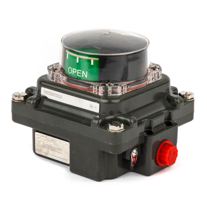
- The indicator dome shows the correct orientation (“OPEN”/“CLOSE”).
- The internal cams trigger the corresponding micro-switches accurately.
If necessary, proceed with cam adjustment.
How to Calibrate a Limit Switch Box
Calibration ensures that the electrical feedback from the limit switch box accurately represents the valve’s actual position. Even the smallest offset can lead to operational errors.
Understanding the Calibration Principle
Inside every limit switch box, two mechanical cams are mounted on a rotating shaft. These cams engage with micro-switches at specific angular positions—usually corresponding to 0° (fully closed) and 90° (fully open).
When the valve actuator rotates, the shaft inside the switch box turns as well, and the cams activate the switches accordingly. Calibration aligns these mechanical and electrical points precisely.
Step 1 – Set the Valve to the Closed Position
- Move the actuator to the fully closed position.
- Remove the limit switch box cover (usually held by 4 screws).
- Observe the internal cam marked “CLOSE.”
If it does not activate the “closed” micro-switch, loosen the cam screw slightly and rotate it clockwise or counterclockwise until it clicks the switch.
Step 2 – Set the Valve to the Open Position
- Move the actuator to the fully open position.
- Adjust the second cam marked “OPEN” to engage the open micro-switch precisely at the end of rotation.
- Tighten the cam screws carefully.
This process ensures that the switch box sends correct electrical feedback at both end positions.
Step 3 – Verify Electrical Signals
Using a multimeter or PLC input, confirm:
- The “OPEN” signal activates only when the valve is fully open.
- The “CLOSE” signal activates only when fully closed.
- There’s no overlap or delay in switch actuation.
If the output appears reversed, simply swap the corresponding terminal wires.
Step 4 – Reassemble and Seal
- Replace the cover gasket (ensure it’s clean and intact).
- Secure the housing screws evenly to maintain enclosure sealing.
- Check that the cable gland or conduit is tightly closed.
KGSY’s IP67-rated housing prevents dust and water ingress, ensuring the calibration remains stable even in harsh environments.
Common Calibration Mistakes and How to Avoid Them
1. Over-Tightening the Cam
If the cam screw is over-tightened, it may deform the cam surface or cause slippage during operation.
Solution: Use moderate torque and verify free rotation after tightening.
2. Ignoring Mid-Range Adjustment
Many operators skip checking intermediate valve positions. In modulating systems, it’s important to verify that the feedback signal (if analog) moves proportionally between open and close.
3. Skipping Electrical Verification
Even if mechanical alignment seems correct, signal errors can occur due to incorrect wiring polarity or poor grounding. Always double-check with a multimeter.
Maintenance and Recalibration Best Practices
Even the best installation needs periodic checks. Limit switch boxes operate under vibration, temperature changes, and humidity, all of which can affect performance over time.
Routine Maintenance Schedule
(Converted from table into text for SEO readability.)
Every 3 months: Check for moisture or condensation inside housing.
Every 6 months: Verify cam and coupling alignment.
Every 12 months: Perform full recalibration and electrical verification.
After maintenance: Apply silicone grease on sealing gaskets.
Environmental Considerations
- In coastal or humid areas, check cable glands and conduit fittings more frequently.
- In explosive environments, ensure that flameproof joints remain intact and certified.
- In high-vibration applications, use lock washers and re-tighten after 100 hours of operation.
Spare Parts and Replacement
Most KGSY limit switch boxes allow modular replacement of cams, switches, and terminals. It’s recommended to use only OEM parts to maintain certification (ATEX, SIL3, CE). Replacement should always be performed with power off and by trained technicians.
Troubleshooting After Calibration
Problem 1 – No Feedback Signal
Possible causes: Incorrect terminal connection; faulty micro-switch; broken cable or poor contact.
Solution: Check terminal block continuity and replace any defective micro-switches.
Problem 2 – Indicator Shows Reverse Direction
If the indicator shows “OPEN” when the valve is closed, simply rotate the indicator 180° or swap the signal labels.
Problem 3 – Signal Delay
This may occur if cams are not firmly fixed or actuator motion is sluggish.
Solution: Tighten cam screws and inspect actuator air pressure or motor torque.
Field Example – KGSY Limit Switch Box Calibration in a Petrochemical Plant
A petrochemical plant in the Middle East required precise valve position feedback to its control system. Engineers used KGSY’s explosion-proof limit switch boxes equipped with gold-plated micro-switches.
Process summary:
- Tools used: torque wrench, multimeter, hex keys, and alignment gauge.
- Installation time per valve: 20 minutes.
- Calibration accuracy achieved: ±1°.
- Result: Improved feedback reliability, reduced signal noise, and enhanced safety compliance.
This case illustrates how professional calibration and high-quality products reduce maintenance downtime by over 40% annually.
Why Choose KGSY Limit Switch Boxes
Zhejiang KGSY Intelligent Technology Co., Ltd. specializes in intelligent valve control accessories and provides comprehensive support from product selection to after-sales calibration.
- Certified to CE, ATEX, TUV, SIL3, and IP67 standards.
- Designed for pneumatic, electric, and hydraulic actuators.
- Equipped with corrosion-resistant enclosures and high-precision cam assemblies.
- Tested under ISO9001-certified production systems.
By integrating engineering precision with global compliance, KGSY ensures that every limit switch box offers long-term performance and accuracy even under extreme conditions.
Conclusion
Installing and calibrating a Limit Switch Box is a delicate but essential part of valve automation. With the right tools, careful alignment, and precise calibration, engineers can guarantee accurate feedback signals and safe plant operation.
Using high-quality equipment such as the products from Zhejiang KGSY Intelligent Technology Co., Ltd., users benefit from consistent reliability, easier installation, and global-standard certifications—ensuring your automation system performs flawlessly for years.
Post time: Oct-07-2025

